Utilizing Fourier-domain interferometry, spectrally encoded endoscopy (SEE) was shown capable of video-rate three-dimensional imaging, albeit at limited depth of field due to the limited spectral resolution of the detection spectrometer. We show that by using dispersion management at the reference arm of the interferometer, the tilt and curvature of the field of view could be adjusted without modifying the endoscopic probe itself. By controlling the group velocity dispersion, this technique is demonstrated useful for imaging specimen regions which reside outside the system’s depth of field. This approach could be used to improve usability, functionality and image quality of SEE without affecting probe size and flexibility.
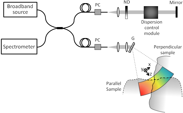
Figure 1: Optical setup for controlling field of view by dispersion management
Our benchtop spectrally encoded imaging system (figure 1) consisted of a broadband titanium sapphire oscillator (Femtolasers Rainbow, 300 nm bandwidth, 800 nm center wavelength) coupled to a 50/50 single-mode optical fiber coupler within a Michelson interferometer arrangement. The sample arm consisted of a fiber collimator, a focusing lens and a 1200 lines/mm transmission diffraction grating (G), with 30º Littrow’s angle at 830 nm. The spectral line was scanned in the y axis by a galvanometric scanner which was placed between the grating and the sample. The reference arm consisted of a collimating lens, a variable neutral density (ND) filter, a dispersion control unit, and a mirror mounted on a translation stage. Interferograms of the reflected spectra from the sample and the reference arms were detected by a custom spectrometer, comprised of a collimating lens, an 1800 lines/mm transmission diffraction grating, a focusing lens and a high-speed line camera (Basler Sprint spL4096).
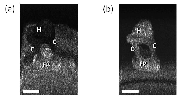
Figure 2: Images of a bovine stapes. Scale bars represent 1 mm. FP – foot plate, C – crus, H – head.
In order to demonstrate effective three-dimensional imaging of a middle ear ossicle without moving the probe, a bovine stapes was attached to a flat surface (figure 2). When an endoscopic probe is inserted into the middle ear through the Eustachian tube, its axis would be nearly perpendicular to the main axis of the stapes which spans along its head, the two crura, and the foot plate. To simulate such configuration, we have imaged the stapes at approximately 90° angle between the probe and the stapes main axis. With no GVD difference between the interferometer arms, the foot plate could be clearly observed (figure 2a), however the two crura, the neck and the head of the stapes, all fall outside the image range and appear dark. With a grating pair separated by 30 mm in the reference arm, the stapes could be fully visualized (figure 2b), while maintaining the same view angle between the probe and the ossicle. The dark horizontal lines on the flat surface below the stapes in figures 2a-b correspond to the reference plane which results with no spectral modulation, and was filtered out by our data processing algorithms.
References
- Dispersion management for controlling image plane in Fourier-domain spectrally encoded endoscopy
Michal Merman and Dvir Yelin
Opt. Express 19, 4777 (2011)